At the microscale, surface forces between objects far exceed volume forces like gravity, making contact adhesion highly likely: two closely positioned objects become difficult to separate due to surface forces. For dry, uncharged surfaces, the van der Waals force is typically the dominant surface force. Because the Van der Waals force hinders and restricts movement, researchers designing mechanical components, especially at the microscale (e.g., MEMS), often increase the separation distance between adjacent surfaces to reduce or avoid interfacial contact adhesion. This ensures smooth component movement without the moving parts getting "stuck."
But can this interfacial adhesion effect be leveraged to drive micro-mechanical systems? Recently, Professor Min Qiu's team at Westlake University proposed a light-manipulation technique that successfully achieved light-controlled oscillatory motion of a microplate utilizing the Van der Waals force. Here, the optical signal acts as the excitation source. Through the photothermal effect, it modulates the Young's modulus of the mechanical system and the Hamaker coefficient. Under the action of the Van der Waals adhesive force, kilohertz-frequency oscillation control of the microplate is achieved, with amplitude control precision reaching the nanoscale. This work was published in ACS Nano under the title "Light-Controlled Oscillation of Microplates Leveraging Contact Adhesion". Dr. Weiwei Tang, a former postdoctoral in Professor Qiu's team and now Associate Researcher at the Hangzhou Institute for Advanced Study, UCAS, and Qiannan Jia, a Ph.D. student in the Zhejiang University-Westlake University joint doctoral program, are the co-first authors. Professor Min Qiu and Researcher Wei Yan of Westlake University are the corresponding authors.
Link to the paper:
https://pubs.acs.org/doi/10.1021/acsnano.5c09198

1. Structural Design of the Light-Controlled Oscillator: Microfiber + Micro Gold Plate Forms a "Micro-Cantilever"
To achieve oscillatory motion in a mechanical structure, constraints must be defined, and specific degrees of freedom should be released. Cantilevers are common basic components for achieving oscillation. For planar contact (Fig. 1a), at the microscale, the effect of surface forces is much greater than gravity. A cantilever extending from a flat substrate, unaffected by surface forces (as it isn't close to another surface), remains straight without significant deformation (gravity as the volume force has minimal effect at this dimension).
When the flat substrate is replaced by a curved substrate, the attached cantilever no longer extends straight but sags linearly (assuming the substrate is below the cantilever). That is, the cantilever undergoes a linearly spatially distributed bending deformation towards the curved substrate, as shown in Fig. 1b. This occurs because the cantilever experiences the Van der Waals force exerted by the curved substrate (upper part of Fig. 1c). The Van der Waals force from the substrate acts as the load on the cantilever. It exhibits characteristics of a short-range force: repulsive (P_vdW > 0) at very small interfacial separations, attractive (P_vdW < 0) at larger separations, decaying rapidly with increasing distance. Because the Van der Waals force is of short-range, and an originally straight cantilever cannot perfectly conform to the curved substrate surface, the force effectively acts only within a narrow contact region (shaded area marked l_ct). Outside this region, the cantilever can be considered free and unloaded (gravity's effect on deformation is negligible). Therefore, beyond the contact region, the cantilever's deformation manifests as linear sagging.
The researchers used a structural mechanics model to simulate the deflection degree (W_end) at the end of a symmetric micro-cantilever (length 20 μm) on curved substrates with different geometric parameters, as shown in Fig. 1d. They found that when the cantilever thickness is small (on the order of hundreds of nanometers) and the curved substrate's radius of curvature is 1-2 μm, the end deflection of the micro-cantilever can reach tens to hundreds of nanometers.
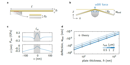
Fig. 1. Basic structure and deformation state of the light-controlled oscillator. a. Cantilever extending from a flat substrate and its deformation state. b. Cantilever extending from a curved substrate and its deformation state. c. Load condition (upper) and deflection (lower) of the microplate/cantilever on the curved substrate. d. Relationship between the end deflection of the microplate/cantilever on the curved substrate and the geometric parameters of the light-controlled oscillator, including the substrate's radius of curvature, and the microplate's/cantilever's thickness and width.
The researchers used a tapered microfiber as the substrate and a micro gold plate as the cantilever placed on the microfiber, forming a simple cantilever structure. This mechanical system consists fundamentally of a curved substrate + a microplate. Furthermore, as the microfiber can transmit optical signals and interact with the gold plate via evanescent fields, generating a photothermal effect, the deformation state of this cantilever system can be modulated by turning the light source on and off (Fig. 2a).
2. Photothermal Excitation Alters Cantilever Deformation State
For the micro-cantilever system shown in Fig. 2a, the sag angle of the cantilever/microplate is closely related to the geometric dimensions of the microfiber and microplate, as well as material and mechanical parameters. Key mechanical parameters include the cantilever's Young's modulus and the Hamaker coefficient of the fiber-gold plate contact interface (characterizing the strength of the Van der Waals force). Based on Euler-Bernoulli beam theory and Hertzian contact theory, the researchers derived an expression for the microplate's sag angle:

Besides geometric parameters, A, E, and Ep correspond to the Hamaker coefficient of the contact interface, the effective Young's modulus of the overall fiber-gold system (E), and the effective Young's modulus of the gold plate (Ep), respectively. These two physical quantities are functions of temperature, meaning they are modulated by the photothermal effect. When the light source is ON or OFF, the cantilever is at different temperatures. Consequently, the Young's modulus in this light-controlled oscillator and the Hamaker coefficient at the contact interface change, leading to a variation in the cantilever's sag angle, as shown in Fig. 2b.
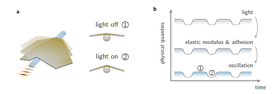
Fig. 2. Operating mechanism of the light-controlled oscillator. a. The oscillator based on the microfiber-micro gold plate system undergoes oscillatory motion modulated by the light switch, specifically showing different deformation states when the light is ON and OFF. b. In the microfiber-micro gold plate system, the gold plate's Young's modulus and the van der Waals force strength at the interface are modulated by the photothermal effect, causing the cantilever/microplate to exhibit different deflections when the light is ON and OFF, thus enabling light-controlled oscillation.
3. Low-Frequency Flapping Motion and High-Frequency Resonance Modes
Using a Digital Holographic Microscope (DHM) (Fig. 3a), the researchers experimentally measured the out-of-plane displacement of the light-controlled oscillator's cantilever and characterized its spatial distribution. Based on the different observed phenomena, they categorized the results by drive frequency: at low optical signal frequencies, the spatial distribution of the cantilever's overall deformation is linear, resembling flapping motion; at high optical signal frequencies, the intrinsic oscillation modes of the cantilever are excited, exhibiting more complex spatial distributions.
For the microfiber-micro gold plate system shown in Fig. 3b, the modulation of the out-of-plane displacement at three points on it by a low-frequency optical signal (1 Hz) is shown in Fig. 3c: when the light turns ON, all points on the gold plate move uniformly towards the fiber, meaning the absolute value of the sag angle θ_d increases; when the light turns OFF, the points return to their original positions. This suggests that in this system, the Hamaker coefficient increases with temperature, and/or the Young's modulus decreases with temperature increase (see formula (1)).
Furthermore, the spatial distribution of the net out-of-plane displacement across the gold plate cantilever is overall linear and symmetric about the fiber-gold plate contact line (Fig. 3d), proving that the Van der Waals force, as a short-range force, is the dominant external force causing the cantilever deformation. Theoretical simulations further ruled out significant contributions from gravity, optical force, and thermal expansion.
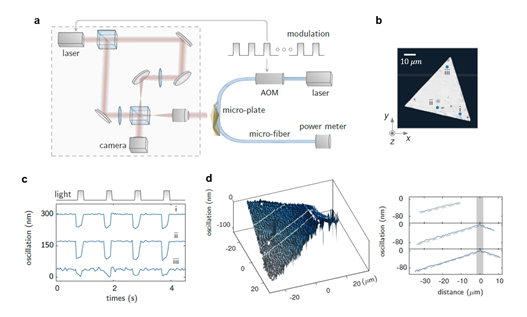
Fig. 3. Low-frequency flapping motion. a. Schematic of the Digital Holographic Microscope (left) and drive optics (right). b. Grayscale optical micrograph of the microfiber-micro gold plate system. c. Relationship between the out-of-plane displacement at three points on the gold plate (marked in b) and the input optical signal (rep rate 1 Hz, duty cycle 20%). d. Spatial distribution of the net out-of-plane displacement across the micro gold plate when the light is ON.
For the system shown in Fig. 4a, when the excitation light's repetition frequency is high, the intrinsic oscillation modes of the oscillator can be excited (the three frames in Fig. 4b). As the excitation frequency changes, the spatial distribution of the vibration evolves accordingly, showing multiple anti-phase vibration regions, nodes, and antinodes in higher-order modes. The researchers used a frequency sweep method, identifying resonance frequencies by detecting sudden peaks in the vibration signal (Fig. 4c). Taking the intrinsic mode at 110 kHz as an example, its quality factor is about 20.1. The time-dependent oscillatory motion of five points on it (see Fig. a) is shown in Fig. 4d. Points 1, 4 and point 2 move in anti-phase, corresponding to the specific spatial distribution of the oscillation mode at that frequency in Fig. 4b. Additionally, the researchers found that the oscillation amplitude increases linearly with the input optical power. This phenomenon occurs stably at both low and high frequencies, and amplitude control via power achieves nanoscale precision (Fig. 4e).
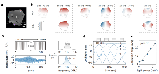
Fig. 4. High-frequency resonance motion. a. Phase map of the microfiber-micro gold plate system captured by DHM. b. Experimentally measured (top) and simulated (bottom) vibration modes at different frequencies. c. Left: Frequency sweep signal (top) and measured vibration signal (bottom) from 100 kHz to 120 kHz. Right: FFT spectra of the sweep signal (top) and vibration signal (bottom). d. Time-dependent oscillatory motion of five points on the gold plate (see b) at the 110 kHz resonance frequency. e. Change in amplitude at point "1" with input optical power.
4. Summary and Outlook
In summary, this research transforms contact adhesion, typically seen as a hindrance to motion, into an effective driving force, achieving controlled oscillatory motion of micro-scale structures via the photothermal effect. The light-controlled oscillator features a simple structure, ease of fabrication, high-frequency response, and nanoscale precision, offering new ideas for applications in micro-robotics, optical micro-mirrors, etc. Given the current lack of reliable experimental methods for in situ measurement of the Van der Waals force and material modulus at the microscale, this work holds promise for quantitatively characterizing these physical parameters by establishing a mapping relation between the oscillator's deformation and the Hamaker coefficient/material Young's modulus.
Source: Westlake University School of Engineering (SOE) Official WeChat Account